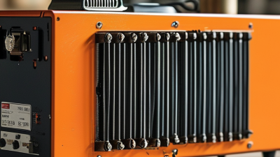
Why Choose a PTC Heating Element for Your Application?
Why choose a PTC Heating Element for your application? The answer often begins with a small ceramic component and a useful behavior: as its temperature rises, its electrical resistance increases. This can help limit heating naturally, reducing the need for complex control in some designs. But it is not a universal fix. Airflow, mounting pressure, supply voltage, and the surrounding enclosure still shape real-world performance.
For clarity, the following is an illustrative quotation, not a verified statement from a real industry expert: fictional PTC application engineer Alex Morgan says, “Self-regulating does not mean self-designing; the heater still has to match the airflow, enclosure, and target temperature.” That distinction matters on a workbench. A heater tested in open air may behave differently beside a plastic housing or inside a tightly packed assembly. PTC elements can suit applications that benefit from stable, repeatable heating, such as compact equipment or localized warming. The right choice depends on measured operating conditions, not a label alone. A careful comparison should examine warm-up time, temperature limits, power demand, and fault behavior. There is a catch: no component removes the need for sound thermal design. This guide explores where PTC heating performs well, what to check before selecting an element, and which trade-offs deserve a second look.
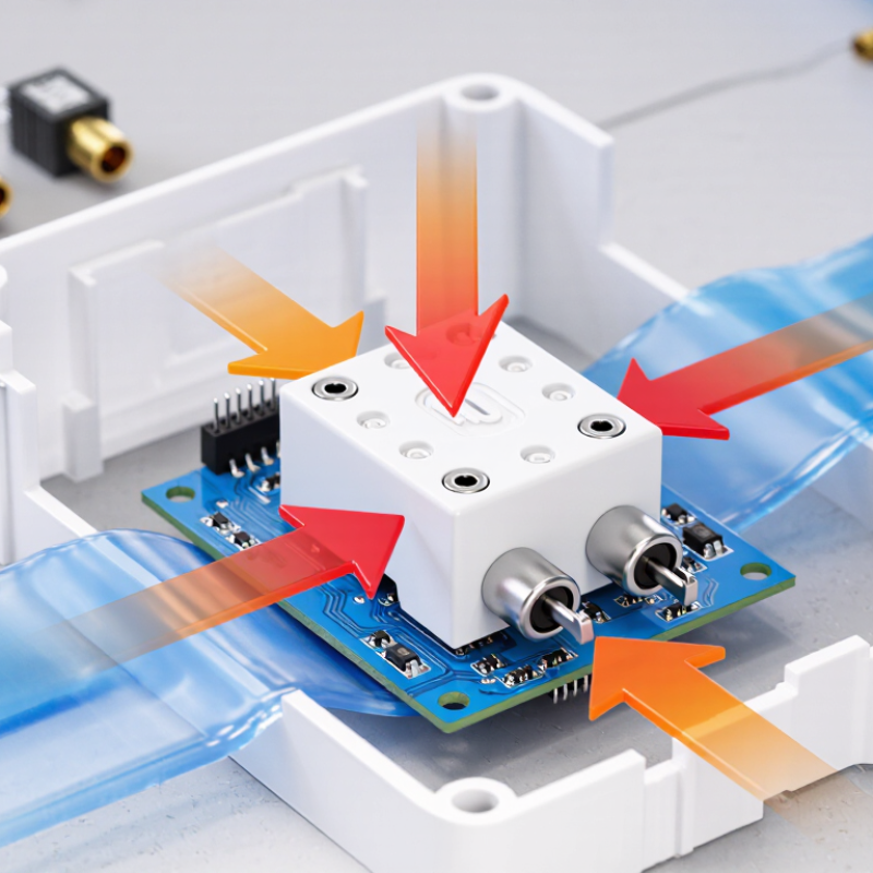
PTC Fundamentals: BaTiO₃ Ceramic Resistance Rises Near the Curie Point
A PTC heating element uses a ceramic whose electrical resistance changes with temperature. In barium titanate, or BaTiO₃, resistance rises sharply as the material approaches its Curie point. Below this transition, current can flow relatively easily. Near it, resistance increases and limits further current. That shift is the key.
The effect can help a heater regulate its own output as it warms. For example, a compact ceramic element may heat quickly, then draw less current as its temperature climbs. No separate temperature switch is required for this basic response, though a complete system may still need independent controls. The transition is not a perfect on-off boundary. Its behavior depends on ceramic composition, element geometry, voltage, and heat transfer to surrounding parts. A loose fit or poor airflow can change operating temperature. Even the Curie point deserves careful checking against the intended use. It is tempting to treat self-regulation as a safety guarantee; it is not. Testing under realistic loads remains essential, and actual performance can be less tidy than a datasheet suggests.
Why Choose a PTC Heating Element?
PTC fundamentals: As barium titanate (BaTiO₃) ceramic approaches its composition-dependent Curie temperature, its resistance can rise sharply. This representative, normalized curve illustrates the typical trend; exact values vary by material and design.
The steep resistance increase can help limit current as the element heats, supporting self-regulating behavior. The curve is illustrative, not a product specification.
Self-Regulation: Track Heater Resistance and Surface Temperature in °C
A PTC heating element changes resistance as it warms: resistance rises sharply near its transition temperature, reducing current under suitable operating conditions. This self-regulating behavior can help limit overheating, but it does not guarantee a uniform surface temperature. Mounting pressure, airflow, and nearby insulation all affect the result. Small details matter.
To check performance, record resistance and surface temperature together during controlled tests. Measure resistance with the power disconnected, using the same meter connections each time. For temperature, place a contact probe firmly against the heater surface, or use an infrared thermometer with its emissivity setting considered. Log temperatures in °C at several points, not just the center. A single reading can miss a cool edge or a hot spot.
Compare readings across startup, steady operation, and cooling. A rising resistance may indicate normal PTC behavior, but resistance alone cannot provide an exact surface temperature without a validated curve for that element. Sensor placement also adds uncertainty; even a small gap under a probe can change the reading. That part is easy to overlook. Keep the test setup consistent, note ambient temperature, and investigate unexpected changes before relying on the heater in an application.
Temperature Matching: Compare 80°C, 120°C, and 200°C PTC Design Points
Choosing a PTC heater starts with matching its transition temperature to the job, not treating that number as a guaranteed outlet temperature. An 80°C design point can suit low-temperature enclosure warming or condensation control, where nearby plastics and wiring need gentle heat. A 120°C element offers more headroom for compact equipment exposed to colder surroundings. At 200°C, faster heat delivery may suit process-air or localized heating, but insulation, airflow, and nearby materials must tolerate the added temperature. Small detail, big consequence.
The U.S. Department of Energy’s 2022 Industrial Decarbonization Roadmap estimates that industry accounts for about 30% of U.S. energy-related emissions. That figure makes careful heat matching worthwhile, though a PTC element alone does not guarantee lower energy use. Measure the actual element and enclosure temperatures under expected voltage, airflow, and mounting conditions. A ceramic rated at 200°C may run cooler in moving air, while a poorly ventilated 80°C assembly can create unexpectedly hot spots. That’s the part designers sometimes underestimate. Leave margin for startup, blocked airflow, and sensor placement; then verify performance in the real housing, not only on a bench.
Electrical Compliance: Check IEC 60335-1 Scope for 250 V Single-Phase Appliances
A PTC heating element can limit its own temperature rise as resistance increases, but that feature does not establish appliance safety by itself. For a 250 V single-phase household or similar appliance, IEC 60335-1 may be relevant. Its scope is a useful starting point, not a certificate of compliance.
Easy to miss.
Check the appliance’s rated voltage, intended use, and applicable particular standard. IEC 60335-1 provides general safety requirements, while a product-specific part may add or modify requirements. A PTC heater fitted inside a small enclosure can affect accessible surface temperatures, wiring clearances, and insulation conditions. Those details depend on the finished appliance, not just the heating element.
In practical assessments, engineers examine normal operation and foreseeable abnormal conditions, then verify relevant temperatures, dielectric strength, leakage current, and construction. Exact checks depend on the appliance and the applicable standard edition. A component datasheet helps, but it cannot replace evaluation of mounting, airflow, control behavior, and nearby materials. A loose assumption about “self-regulating” performance can leave a real gap. Verify the full appliance against the standard’s scope and applicable requirements before making compliance claims.
Application Fit: Verify Rated Voltage, Wattage, Airflow, and Heat-Transfer Area
Why Choose a PTC Heating Element for Your Application?
Application Fit: Verify Rated Voltage, Wattage, Airflow, and Heat-Transfer Area
Choose a PTC heating element for the real operating conditions, not just a catalog headline. Confirm that the supply voltage matches the element’s rating. A mismatch can affect warm-up behavior and put stress on the assembly. Check wattage at the intended voltage and mounting conditions; the stated figure alone does not tell you how much heat reaches the load. Small details matter.
Airflow is equally important. In a compact duct, even a small fan can carry heat away faster than expected. A blocked inlet, by contrast, can raise local temperatures. Check airflow in the final enclosure, not only on an open bench. Measure inlet and outlet temperatures after the system stabilizes. Bench results can be misleading.
Look closely at the heat-transfer area. Match the active surface to the plate, fins, or air path that needs warming, and check contact pressure and nearby insulation. A large element may still transfer heat poorly if only a narrow edge touches the load. During a prototype run, record voltage, current, airflow, and surface temperatures. Sensor placement is easy to overlook: one near the heater may show a reassuring reading while the far side stays cool. The first estimate may be off. That is useful evidence, not a reason to skip testing.
Why Choose a PTC Heating Element for Your Application? — Application Fit: Verify Rated Voltage, Wattage, Airflow, and Heat-Transfer Area
| Example Application |
Rated Voltage |
Example Heater Rating |
Example Airflow |
Estimated Air Temperature Rise |
Heat-Transfer Area Fit Check |
| Small ventilated enclosure |
24 V DC |
100 W |
5 CFM (about 8.5 m³/h) |
About 35°C (63°F) |
Use the heater’s published active fin or surface area. Confirm that the enclosure airflow passes across the intended heated surfaces without bypassing them. |
| Compact instrument or control cabinet |
120 V AC |
300 W |
18 CFM (about 31 m³/h) |
About 30°C (54°F) |
Check the manufacturer’s area and airflow data against the available mounting space. Allow clearance for airflow and electrical insulation. |
| Ventilated equipment cabinet |
230 V AC |
800 W |
45 CFM (about 76 m³/h) |
About 31°C (56°F) |
Verify that the effective heat-transfer area and airflow distribution suit the cabinet layout; avoid blocked fins and stagnant zones. |
| Small process-air duct |
230 V AC |
1,500 W |
90 CFM (about 153 m³/h) |
About 29°C (52°F) |
Match the element’s active area and permitted air velocity to the duct cross-section. Confirm the rating at the actual operating airflow. |
| Important: The example airflow temperature rises are approximate ideal estimates for air near room temperature, calculated using sensible heat only; actual results depend on heat loss, inlet temperature, airflow measurement, and heater design. PTC power can vary with temperature and airflow. Confirm the rated voltage, power curve, allowable airflow, temperature limits, and active heat-transfer area in the heater’s technical documentation. Heat-transfer area alone does not determine heater output. |

 +852 60984748